Gradient Mesh
A gradient mesh is an object filled with a smooth transition between colors arranged into a grid with nodes at arbitrary locations. A mesh consists of a grid of nodes, and curved shapes defining the sides of the grid or the edges between the nodes. The nodes of the grid can be positioned freely, and each node can be assigned a color. The interior of the mesh is filled with a color transition using the color of the mesh nodes and the distortions caused by the curved mesh edges.
The edges of the mesh may contain any sequence of cubic, quadratic or line segments. Typically a mesh edge consists of a single segment, but in VectorStyler, the edges may be made of multiple segments, creating complex shapes.
The opacity of the mesh is determined by the opacities set at the mesh nodes. Each mesh node can be assigned with a separate opacity value. The opacity amounts over the mesh area are determined by smoothly transitioning between opacity values set at the nodes, considering the edge curvatures.
Create a Mesh Object
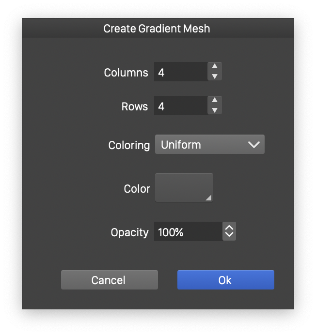
Creating a new gradient mesh.
A new mesh object can be created using the Create Gradient Mesh command of the Styles menu. The mesh can be created from any object filled with a solid color and having a single closed shape.
To create a new mesh object use the following steps:
- Select the object with a single shape, and preferably filled with a solid color. The fill and outline styles of the object will be removed.
- Select the Create Gradient Mesh command from the Styles menu.
- Set the initial size of the mesh grid in the Columns and Rows fields.
- Set the initial coloring mode of the mesh nodes in the Coloring field.
- Set the initial color of the mesh nodes in the Color field. The mesh nodes are colored using the current object color and the selected color, either by using the same color (Uniform), or transitioning between the object color and the selected color towards center (To Center) or towards the object edges (To Edge).
- Set the initial opacity amount in the Opacity field. The mesh node opacities are set in a similar way as the mesh node colors, using the mode selected in the Coloring field.
- To create a new mesh object, confirm the initial mesh settings by pressing the Ok button.
As the new mesh object is created, the Gradient Mesh tool is selected automatically, to enable the editing of the mesh nodes.
The Gradient Mesh Tool
The Gradient Mesh  tool, from the application toolbox, can be used to interactively create and edit gradient mesh objects. Gradient mesh objects are edited by selecting and moving the mesh nodes and adjusting the mesh edge curves, in a similar way as the Node tool is used to edit object shapes.
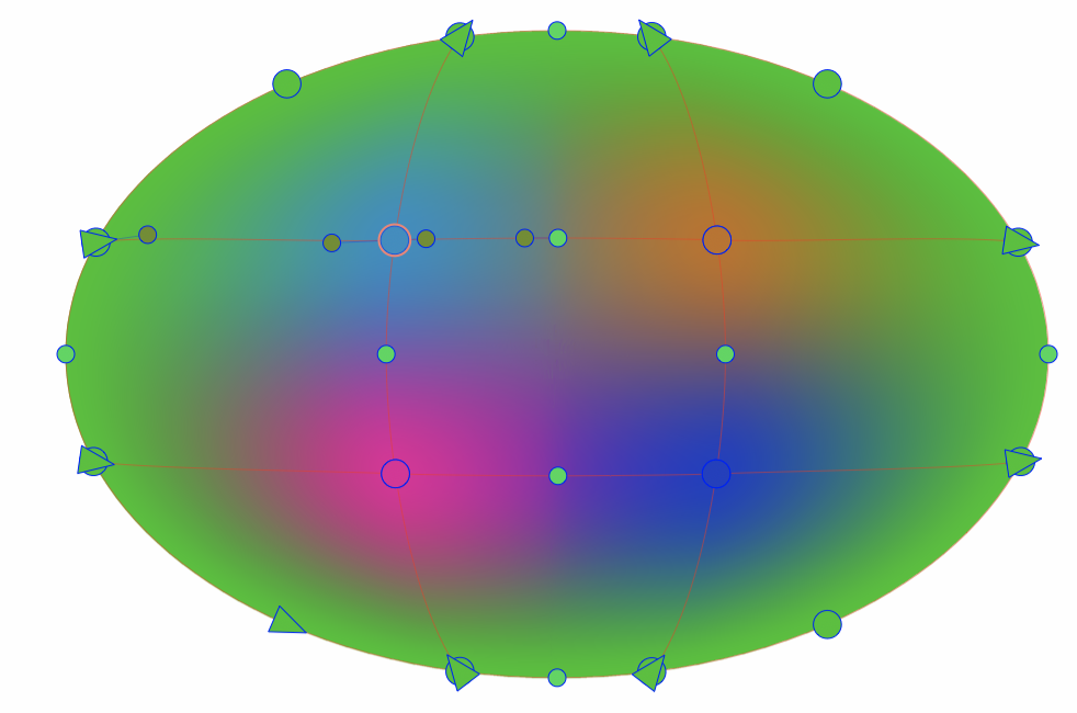
Nodes of a gradient mesh object.
When the mesh tool is selected, clicking on an object will automatically convert that object into a mesh object. When creating the mesh object, a new mesh node is inserted at the clicking location of the object. The new mesh object will consist of the four corner nodes and an inner node, with edges shaped according to the original object shape. To create a mesh object, without inserting a new mesh node hold the Command (Mac) or Control (Windows) key, while clicking on the object.
When the gradient mesh tool is active, the mesh nodes and edges are visible, and can be selected and adjusted. The mesh nodes are rendered slightly larger than the regular path nodes, to indicate that these nodes can be assigned colors, while regular path nodes cannot. Each mesh node is rendered using the color assigned to that node.
The following mesh editing options are available while using the mesh tool:
- To change the position of a mesh node, select the node by clicking on it and start dragging the node with the mouse. As the position of a node is changed, the color transitions are updated automatically.
- To change an edge of the mesh, select any location of the edge and start dragging the location with the mouse. A mesh edge is similar to a path shape, consisting of one or more segments. Segments can be cubic or quadratic curves or lines. An edge is edited by moving its nodes around, or by reshaping segments using any location of a segment.
- To edit the segment and node properties of a mesh edge, use the path editing commands from the Path panel. These commands can be used to change the type of a path node to cusp, smooth or symmetric, or to change the type of a segment to line, quadratic or cubic.
- To set the color of a mesh node, select the mesh node and select a color from the Color panel, Color Palette or the Styles or Presets panels. The mesh node colors are selected using the same tools as the selection of object fill colors.
- Mesh node colors can be also assigned from color styles and reference object fills, enabling the dynamic styling of gradient meshes. When using color styles, the gradient mesh is automatically updated as the color styles are changed.
- To set the opacity of a mesh node, select the mesh node and select the opacity value from the transparency panel.
- To insert a new node into the mesh grid, double click at any location inside the mesh. If the double click is located on a mesh edge, new nodes are inserted in either horizontal or vertical direction, depending on the edge. If the double click is located inside the mesh, new nodes are inserted in both horizontal and vertical directions, increasing the mesh grid size.
- To remove a mesh node, select the node and press the Delete key.