Outline Effects
The Outline section of the shape effects, contains a set of parametric outline adjustment effects. These effects will adjust the outlines of the objects individually, creating new shapes from the existing object shapes.
In some of these shape effects, the primary shape effect  tool can be used to adjust shape effect attributes interactively.
Center Line
The Center Line outline effect can be used to create a center line of a closed shape (also known as straight skeleton). The center line will be a set of line segments at equal distance from the original shape, the line segments opationally approximated by curves.
The Center Line is a non-destructive shape effect, if the original shape changes, the center line will be automatically updated. To get the actual curves making up the center line, use the Convert to Curves command.
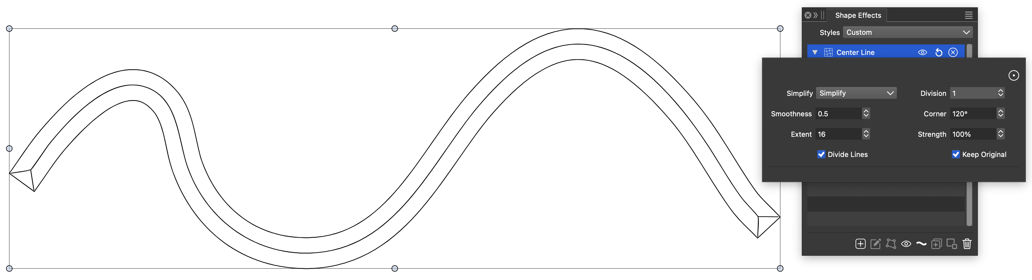
The Center Line effect.
The Center Line effect uses the following options:
- Simplify - Set the line sequence simplification method. This option can be used to select how the lines are approximated with curves.
- Division - Set the source shape division factor. Higher division factor creates more precise center lines, at the expense of computation time.
- Smoothness - Set the line approximation smoothness factor.
- Corner - Set the sharp corner angle when creating curves.
- Extent - Set the line sequence smoothing window.
- Strength - Set the line sequence smoothing factor.
- Divide Lines - Check to also subdivide paths containing only lines.
- Keep Original - Check to keep the original shape.
Extract Parts
The Extract Parts outline effect can be used to cut a shape into multiple parts. For example: this effect can be used on a Stroke style in the Appearance panel, to cut parts of the path for that stroke only.
The Extract Parts is a non-destructive shape effect, where the original shape remains editable, automatically updating the extracted parts. The Extract Parts effect can also be edited interactively, using the Shape Effect tool.
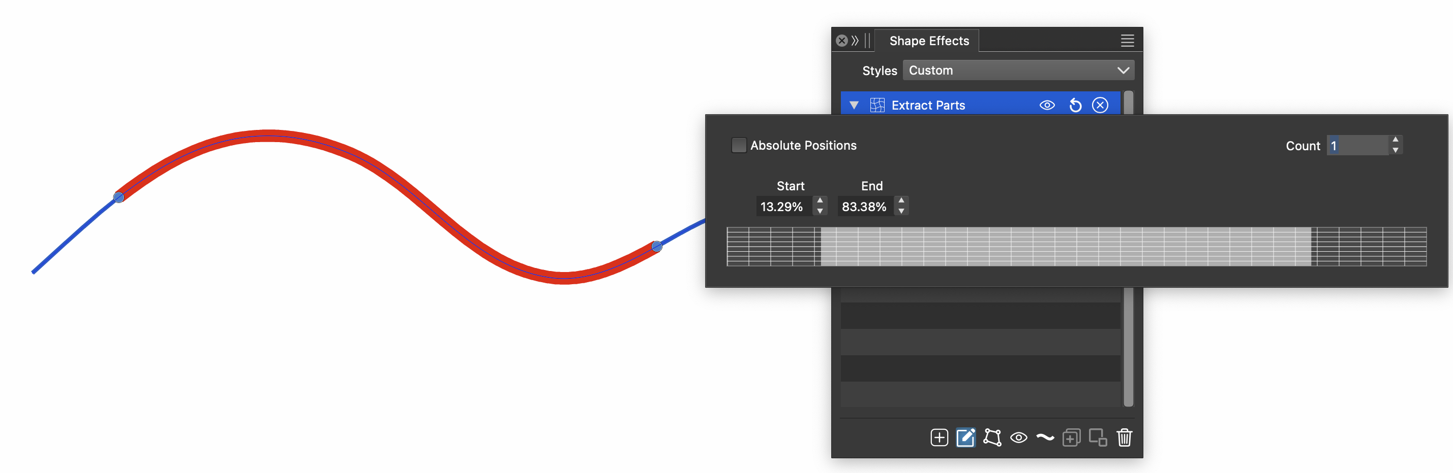
The Extract Parts effect.
The Extract Parts effect uses the following options:
- Absolute Positions - Check to set the extracted part position and length in absolute values. When unchecked, the start and length are set relative to the original path length.
- Count - Set the number of extracted path sections.
- Start and End - Set the starting and ending location of an extracted part.
- Drag the slider in the view to adjust starting and ending positions.
The Extract Parts effect can be edited interactively, using the primary shape effect editor tool from the panel. Each extracted path section is marked with a starting and ending knob, that can be dragged to adjust the extracted part start and end.
Spiral Offset
The Spiral Offset outline effect can be used to create a spiraling offset of a shape. The Spiral Offset is a non-destructive shape effect, where the original shape remains editable, automatically updating the spiraling offset.
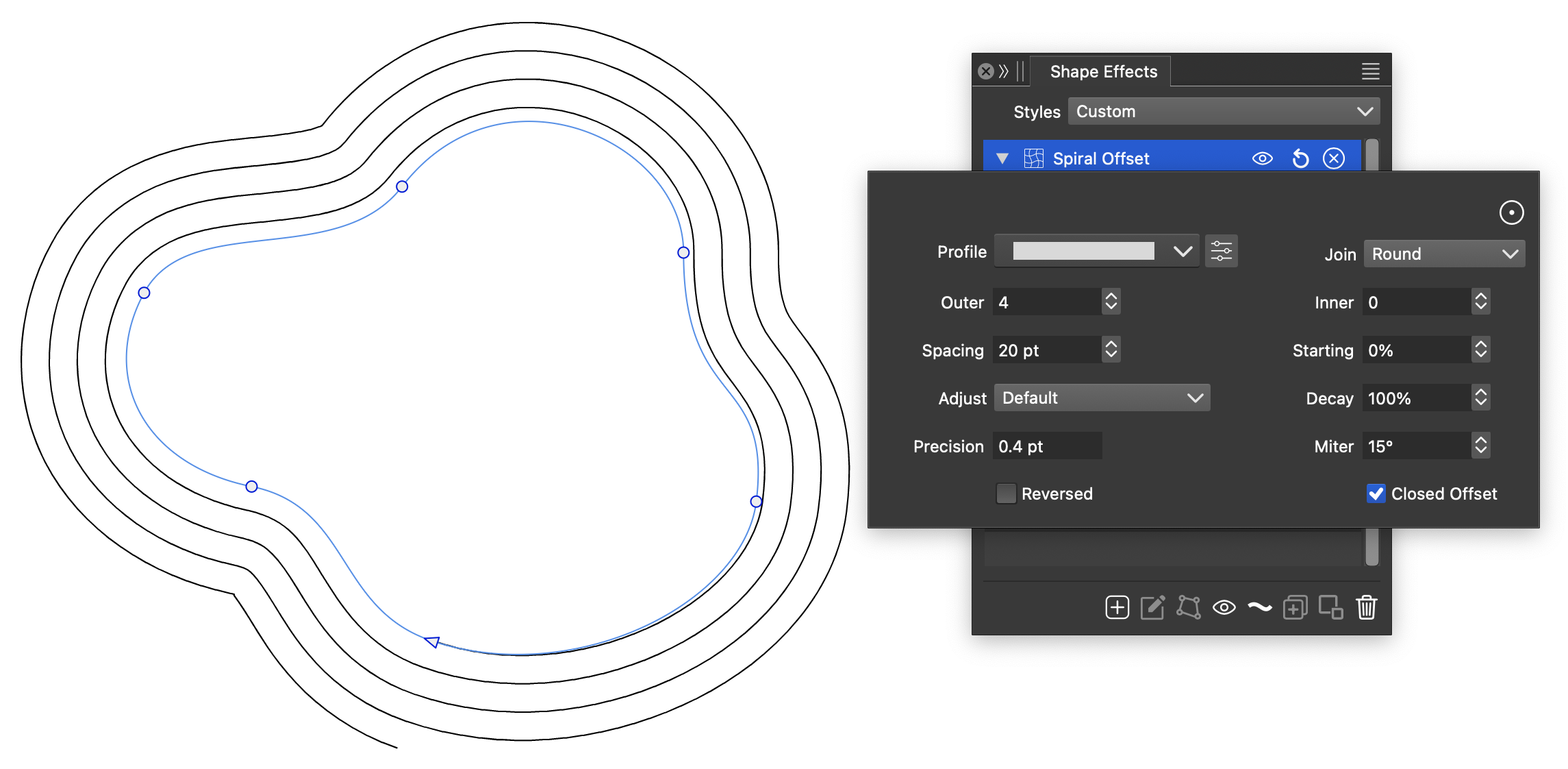
The Spiral Offset shape effect.
The Spiral Offset effect uses the following options:
- Profile - Select the variable width profile used when creating spiral offset iterations.
- Join - Set corner joining mode when offsetting sharp corners.
- Outer - Set the outer iterations of the spiral offset.
- Inner - Set the inner iterations of the spiral offset.
- Spacing - Set the amount of spacing between the spiral offset iterations.
- Starting - Set the starting location of the spiral offset, when offsetting closed shapes.
- Adjust - Select the spacing adjustment function.
- Decay - Set the spacing decay factor.
- Precision - Set the offsetting precision.
- Miter - Set the sharp corner offsetting miter angle.
- Reversed - Check to create the spiral offset in reversed direction.
- Closed Offset - Check to create the spiral offset on closed shape.
Crossing Gap
The Crossing Gap outline effect can be used to remove parts of the curve at self intersection locations.
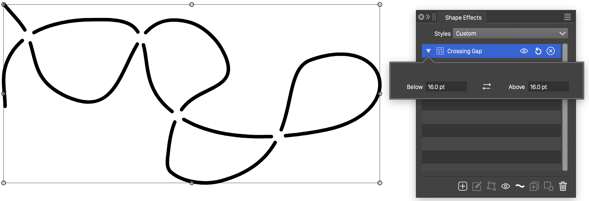
The Crossing Gap outline effect.
The Crossing Gap outline effect uses the following options:
- Below - Set the gap created when crossing below.
- Above - Set the gap created when crossing above.
Curvature Scale
The Curvature Scale outline effect can be used to smooth curves using averaging over a section of the curve.
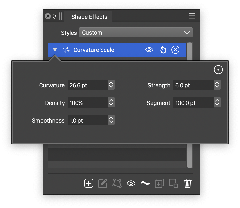
The Curvature Scale effect options.
The Curvature Scale outline effect uses the following options:
- Curvature - Select the curvature adjustment extent along the path.
- Density - Flattening density, the curvature effect flattens the curves into points.
- Smoothness - Amount of low level detail in the simplified shape.
- Strength - Select the curvature adjustment distribution.
- Segment - Maximum segment length limit. Longer segments are split into half.
Detail
The Detail outline distortion effect adds or removes low level details of shapes. The low level details are adjusted by keeping high level aspects of the shape intact. The level of detail to keep or adjust can be selected by the user.
The Detail effect can also be used to copy low level detail from other shapes.
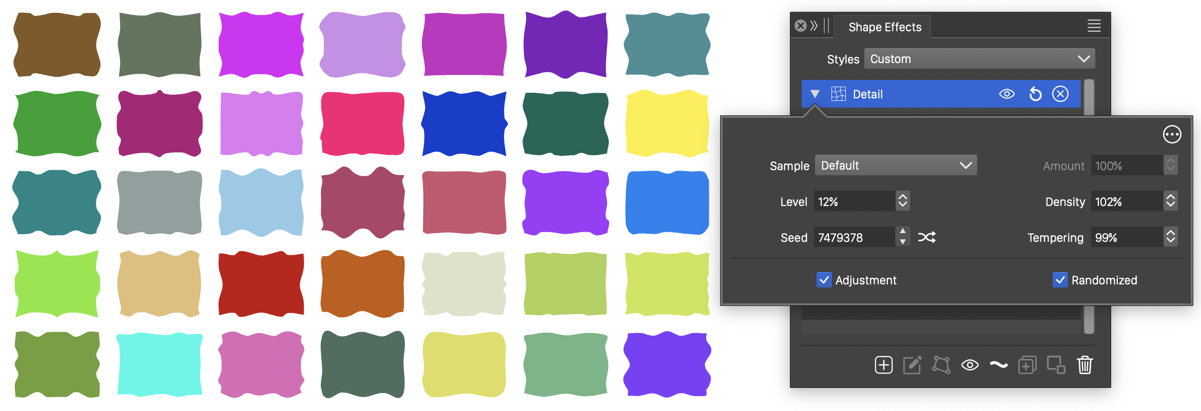
The Detail outline distortion, with basic options.
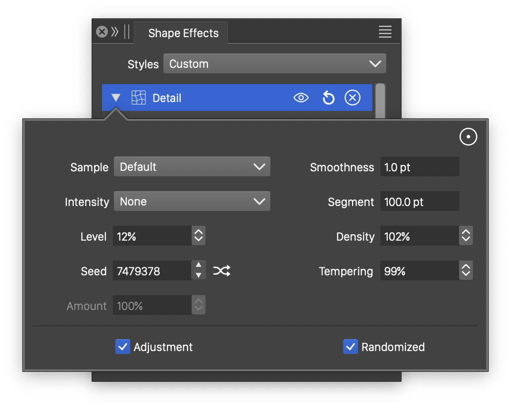
Advanced options of the Detail outline distortion.
The Detail outline effect uses the following basic options:
- Sample - Select the sample shape used to adjust high level details of the filtered shapes. The sample shape can be selected from the list of shape presets, styles and object references with the Shape role. This option is enabled only if the Adjustment option is selected.
- Density - Edit the density of the sampling of both the filtered shapes and the detail sample shape.
- Level - Edit the amount of high level detail to keep from the original shape. The low level details are adjusted randomly or by the sample shape, depending on the selected options.
- Tempering - Edit the strength of randomization of the low level shape details.
- Seed - Set the randomization seed used to generate low level details. The
 button can be used to pick random seed values.
 - Adjustment - Enable or disable the adjustment of the filtered shape using low level details from the selected sample shape.
- Randomized - Enable or disable the adjustment of the filtered shape using randomly generated low level details.
More advanced options of the Detail distortion are available, by clicking on the  button.
- Intensity - Select a function to adjust the intensity of low level detail changes. The Cubic and Monotone Cubic functions are edited by selecting the Edit Curve command.
- Smoothness - Edit the smoothness of the reconstructed curve shapes.
- Segment - Edit the maximum segment length. Longer segments are split into shorter parts.
- Amount - Edit the strength of the low level details copied from the sample shape.
Displacement
The Displacement outline distortion effect moves locations of a shape using a mask image created from an other object. The amount of movement of shape positions can be controlled locally, by the color intensity of the mask object. The Displacement effect can be used for example, to create a relief of a mask in a set of outlines.
Any user created object (or group of objects) can be used as the displacement mask, by assigning a name to the object, and enabling the Filter Image role for the object with the Object Options command.
Modifying or editing the mask object will automatically update all displacement effects using the mask.
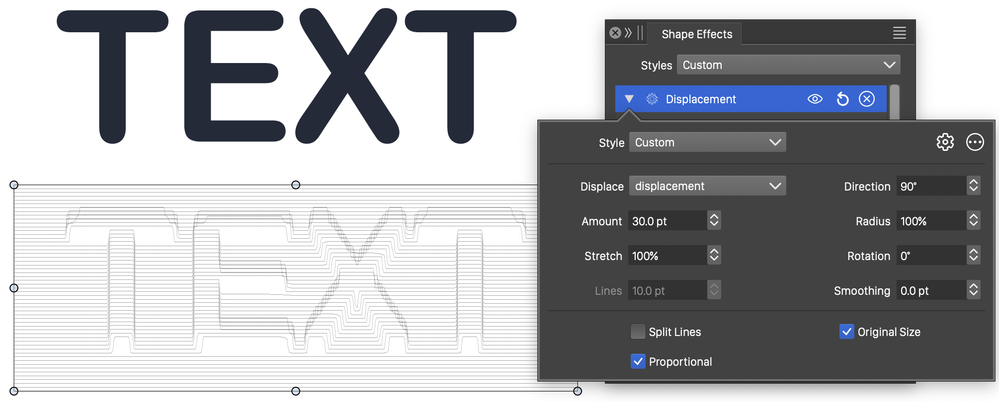
The Displacement outline distortion, with basic options.
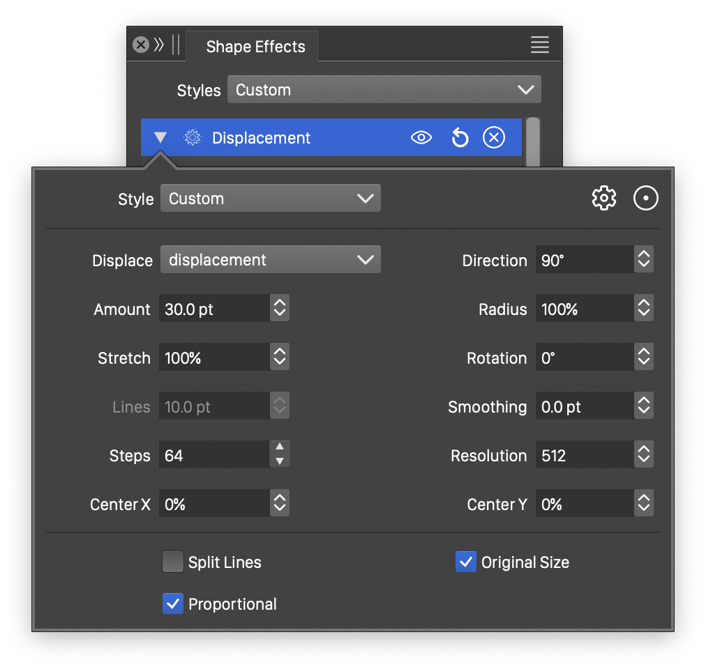
Advanced options of the Displacement outline distortion.
The Displacement outline effect uses the following basic options:
- Displace - Select the displacement mask object. This field opens a list of objects with the Filter Image role, from the current document. Typically these objects are placed on a reference sheet.
- Radius - Edit the radius of the displacement mask, relative to the extend of the distorted outlines.
- Amount - Edit the maximum amount of displacement.
- Rotation - Edit the rotation of the displacement mask.
- Direction - Set the direction of the displacement of outline points.
- Smoothing - Set the amount of extra smoothing applied to the displaced outline nodes.
- Lines - Set the maximum length of lines created when the Split Lines option is enabled.
- Split Lines - Enable or disable the splitting of lines into multiple smaller length lines. When enabled, the displacement effect splits the lines of shapes into smaller lines (limited by the length in the Lines field). The displacement mask relief is then approximated using these lines, creating a sharp relief. When disabled, the displacement mask relief is approximated using smooth curves.
- Proportional - Enable or disable the proportional fitting of the displacement mask to the distorted outline region.
- Original Size - Enable or disable the use of the original displacement mask size.
More advanced options of the Displacement distortion are available, by clicking on the button.
- Stretch - Edit the amount of vertical stretching of the displacement mask.
- Steps - Edit the maximum number splits made on a single curve segment.
- Resolution - Edit the resolution of the displacement mask.
- Center X and Center Y - Set the center of the displacement distortion.
The displacement mask can be interactively positioned, sized, rotated and stretched, using the primary shape effect editor tool:
- Click on the original shape at any location and drag to set the offset distance.
- If the distance is uniform (default width profile), hold the Command (Mac) or Control (Windows) key and click at a location on the shape to add a different, non-uniform distance at that location.
- If the distance is non-uniform, clicking at a location will add a new width node and a local offset distance.
- The width nodes can be dragged and positioned along the shape to set the location of various offset amounts.
The button from the Shape Effects panel, activates the shape effect tool used to interactively edit the circular bump distortion attributes.

Interactive editing of the Displacement effect.
Interactive editing of the displacement distortion is done by dragging the handles to change an attribute value:
- (1) - Set the vertical stretching of the displacement mask, by dragging this handle towards or away from the center.
- (2) - Set the center of the displacement mask.
- (3) - Set the radius of the displacement, by dragging this handle towards or away from the center.
- (4) - Set the rotation of the displacement mask, by dragging this handle around the center.
- (5) - Set the amount of displacement, by dragging this handle along the axis of the displacement rotation.
Node Bump
The Node Bump distortion effect shifts nodes and control points towards or away from the center of each shape. The amount of shifting adjustment can be selected by the user.
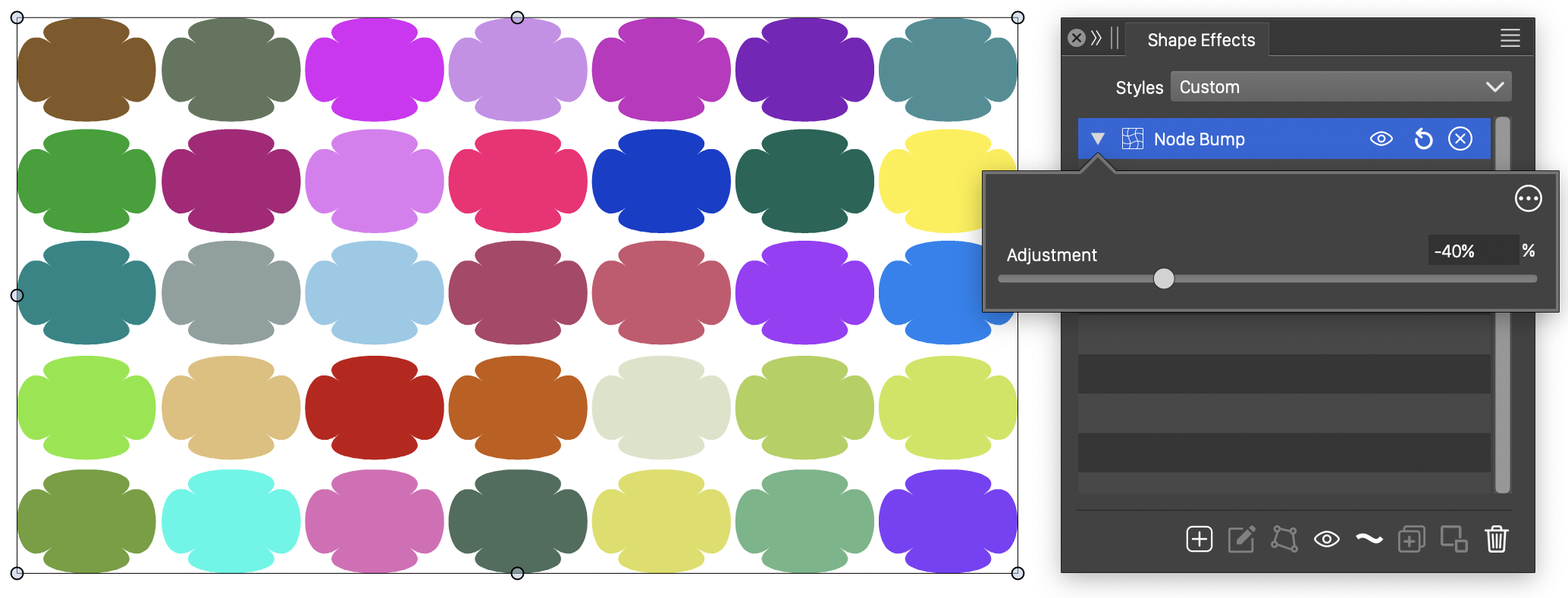
The Node Bump distortion, with basic options.
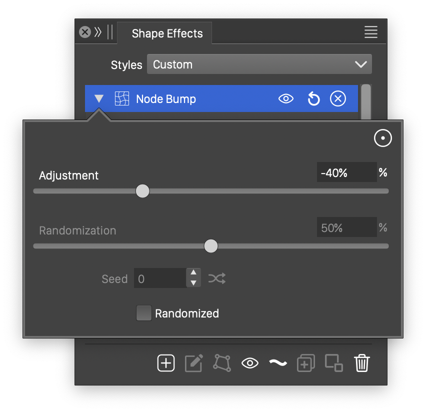
Advanced options of the Node Bump distortion.
The Node Bump effect uses the following basic options:
- Adjustment - Set the amount of shifting of the nodes away from the shape center and control points towards the shape center.
- Randomization - Set the amount of randomization used in the node and control point position adjustment.
- Center - Set the center of the node bump effect.
- Seed - Set the randomization seed.
- Randomized - Enable or disable the randomization of node and control point position adjustments.
- Global Center - Check to apply a node bump effect on a group using a common center.
The node bump effect can be edited interactively, using the primary shape effect editor tool:
- Adjust the center of the effect by dragging the (x) knob.
- Adjust the strength of the effect by dragging the round knob along the strength axis.
Offset Path
The Offset Path outline effect offsets the object outlines outwards or inwards by a user defined amount. A variable width profile can be used to create non-uniform outline offset effects.
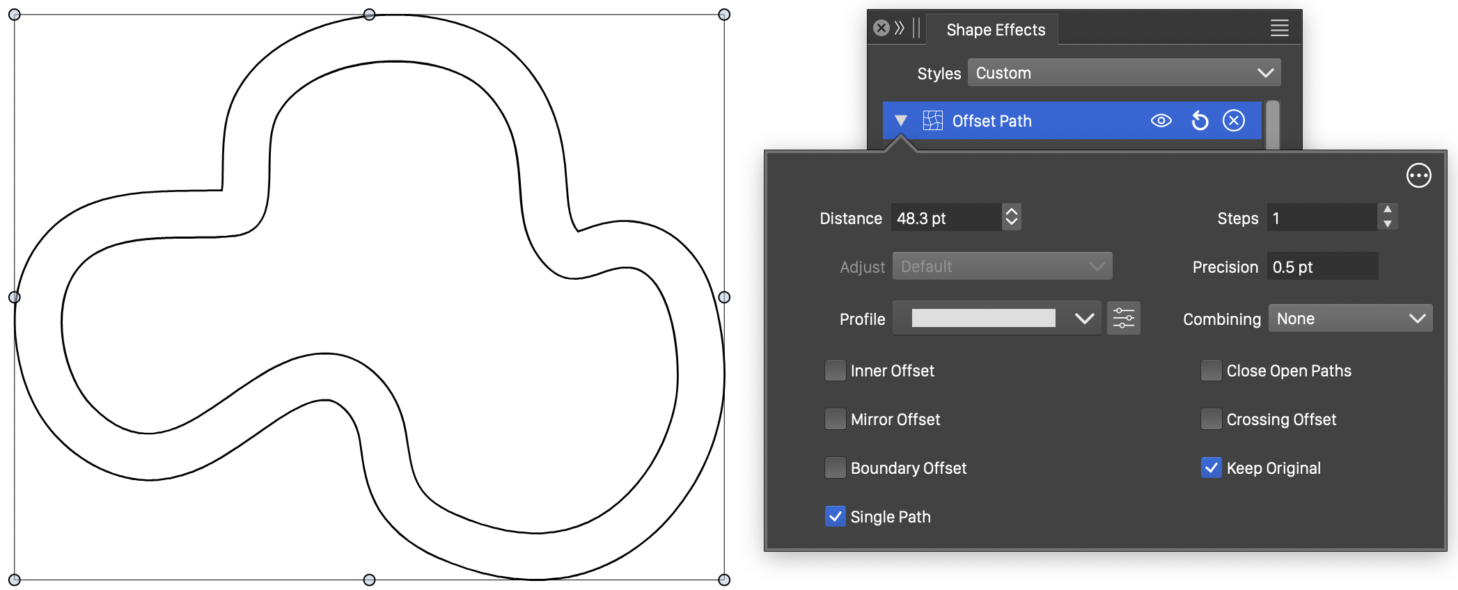
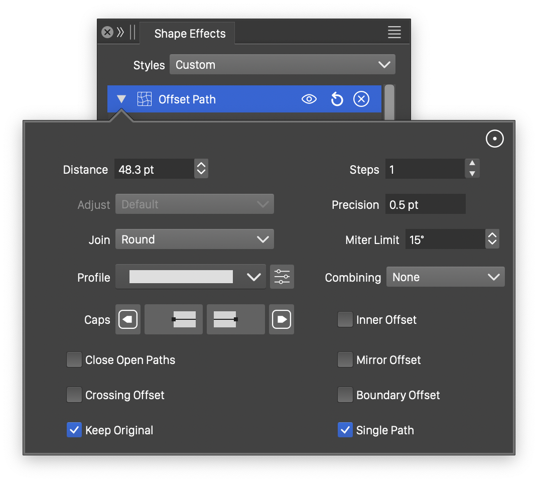
The Offset Path outline effect, with basic options.
Advanced options of the Offset Path outline effect.
The Offset Path outline effect uses the following basic options:
- Distance - Edit the shape offsetting distance. Positive distances will offset closed shapes outwards. Negative distances will offset closed shapes inwards.
- Steps - Set the number of offsets to create using the distance as spacing.
- Adjust - Select a distance distribution function when more than one offset steps are used. The distance distribution function can be used to decrease or increase the distance variation of multiple offsets.
- Precision - Edit the precision used to calculate the shape offsets. The precision value is used to select between approximating the ideal shape offset or using as few new shape nodes as possible.
- Profile - Select the variable width profile preset or style, used in the shape offsetting. The variable width profile controls the variation of the distance of the offset shape. To set custom variable width profiles, click on the
 button, or use the primary shape effect editor tool.
 - Combining - Select the path combination phase used when there multiple paths in the offset. This can be:
- None - offsetting each path separately.
- Before - create a union of the multiple paths first, and then an offset of the union.
- After - create an offset of each path, and then an union of the resulting offsets.
- Inner Offset - Create the offset on the other side of the shape. For closed shapes, this can be the inner side, for positive offset distances.
- Closed Open - Create closed offsets for open shapes, by turning around the endings.
- Double Open - Create offsets on both sides of the shape.
- Keep Original - Keep the original shape also.
More advanced options of the Offset Path effect are available, by clicking on the button.
- Initial - Set the initial offset distance. The shape offsets are calculated by adding this initial distance.
- Miter Limit - Set the miter limit angle when expanding sharp angles. Angles below this limit always result in round or bevel corners when expanded.
- Join - Select the offsetting mode of sharp corners. The offsetting modes are the same as the stroke corner modes for sharp corners.
- Cap - Select or edit the stroke cap shape used when expanding open paths. The editing and selection of stroke caps is described in more detail in the Stroke Caps section.
The shape offset distance can be edited interactively, using the primary shape effect editor tool:
- Click on the original shape at any location and drag to set the offset distance.
- If the distance is uniform (default width profile), hold the Command (Mac) or Control (Windows) key and click at a location on the shape to add a different, non-uniform distance at that location.
- If the distance is non-uniform, clicking at a location will add a new width node and a local offset distance.
- The width nodes can be dragged and positioned along the shape to set the location of various offset amounts.
- The width at the selected width node can also be changed using the Stroke Width panel.
Outline Path
The Outline Path outline effect creates an expanded stroke effect using the stroke attributes on the shape outlines. When creating outline effects, all the stroke attributes described in the Outlining chapter are available for selection.
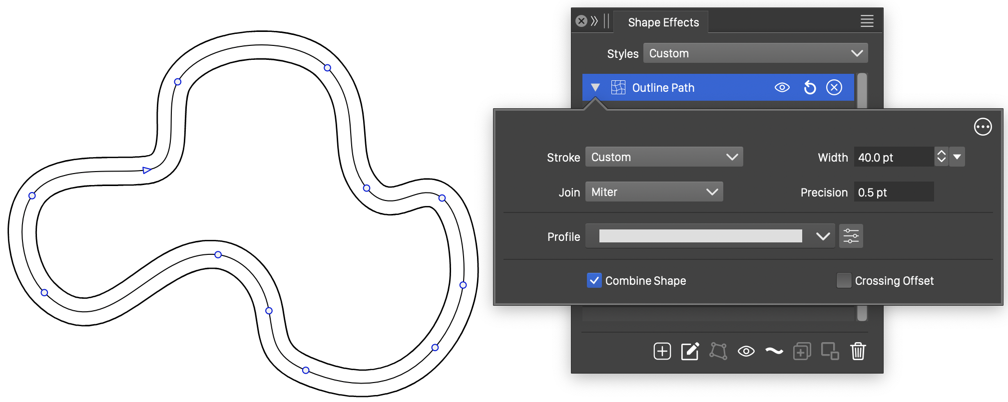
The Outline Path effect, with basic options.
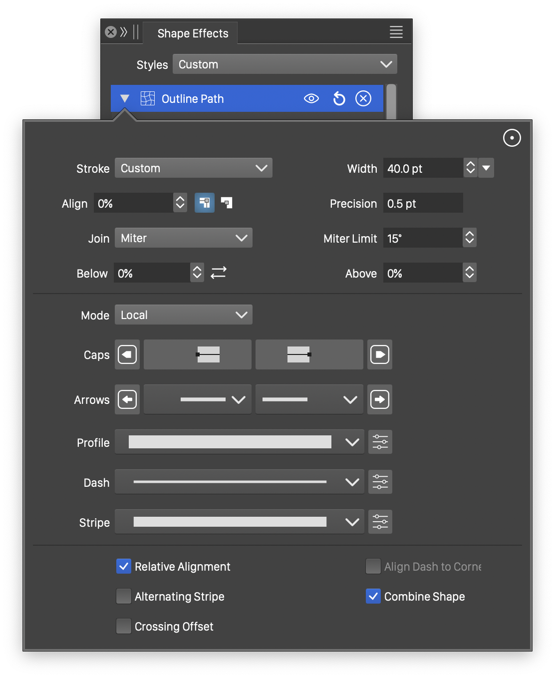
Advanced options of the Outline Path effect.
The Outline Path effect uses the following basic options:
- Stroke - Select a stroke style or preset from the list. Stroke styles and presets can also be created in the Stroke panel, and reused in the outline path effect. The Edit Stroke option from the opened menu opens the stroke selector modal view, to edit all stroke attributes.
- Width - Edit the outline stroke width.
- Precision - Edit the precision used to calculate the outline stroke. The precision value is used to select between approximating the ideal outline stroke or using as few new nodes as possible.
- Join - Select the outlining mode of sharp corners. The outlining modes are the same as the stroke corner modes for sharp corners.
- Profile - Select the variable width profile preset or style, used in the outline stroke. The variable width profile controls the variation of the outline width. To set custom variable width profiles, click on the button, or use the primary shape effect editor tool.
- Combine Shape - Check to combine composite shapes into a single path, to create a unified outline stroke.
More advanced options of the Outline Path effect are available, by clicking on the button.
- Align - Set the alignment of the outline shape relative to the original outline. Alignment can be centered, inside or outside, or any user specified distance from the original outline.
- Miter Limit - Set the miter limit angle when expanding sharp angles. Angles below this limit always result in round or bevel corners when expanded.
- Mode - Select the outline stroke generation mode. This can be:
- Raw - Do not cleanup local self-intersection of the outline shape.
- Local - Do a local cleanup self-intersection points of the outline shape.
- Global - Do a global cleanup of the resulting outline shape, considering the winding fill rule.
- United - In addition to a Global cleanup, merge composite shapes using the path union operator.
- Cap - Select or edit the stroke cap shape used when outlining open or dashed shapes. The editing and selection of stroke caps is described in more detail in the Stroke Caps section.
- Dash - Select or edit a stroke dash style or preset used in the shape outlining. The editing and selection of stroke dashes is described in more detail in the Stroke Dashes section.
- Stripe - Select or edit a stroke stripe style or preset used in the shape outlining. The editing and selection of stroke stripes is described in more detail in the Stroke Stripes section.
- Relative Shift - Enable or disable the relative alignment amount of the stroke outline. When enabled, the stroke outline alignment is set relatively to the outline width. When disabled, the alignment is set using an absolute value, independent of the outline width.
- Align to Cusp - Enable or disable the alignment of dashes to cusp nodes.
- Alternating Stripe - Enable or disable the use of alternating stripes, when both stripe and dash styles are defined.
The outline stroke width can be edited interactively, including the definition and adjustment of variable width nodes, using the primary shape effect editor tool:
- Click on the original shape at any location and drag to set the outline width.
- If the width is uniform (default width profile), hold the Command (Mac) or Control (Windows) key and click at a location on the shape to add a different, non-uniform width at that location.
- If the width is non-uniform, clicking at a location will add a new width node and a local width amount.
- The width nodes can be dragged and positioned along the shape to set the location of various width values.
- The width at the selected width node can also be changed using the Stroke Width panel.
Outline ZigZag
The Outline ZigZag outline effect adds a zigzag variation to the shape outlines. The shape variation mode can be sharp, smooth or randomized. The outline variation can be added in multiple parallel versions, using outline stripe styles.
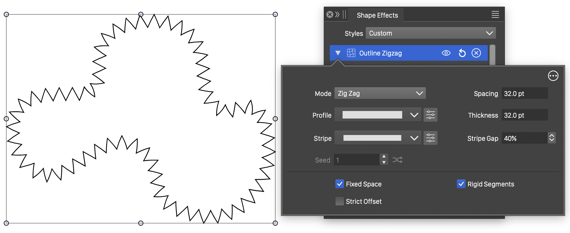
The Outline ZigZag effect, with basic options.
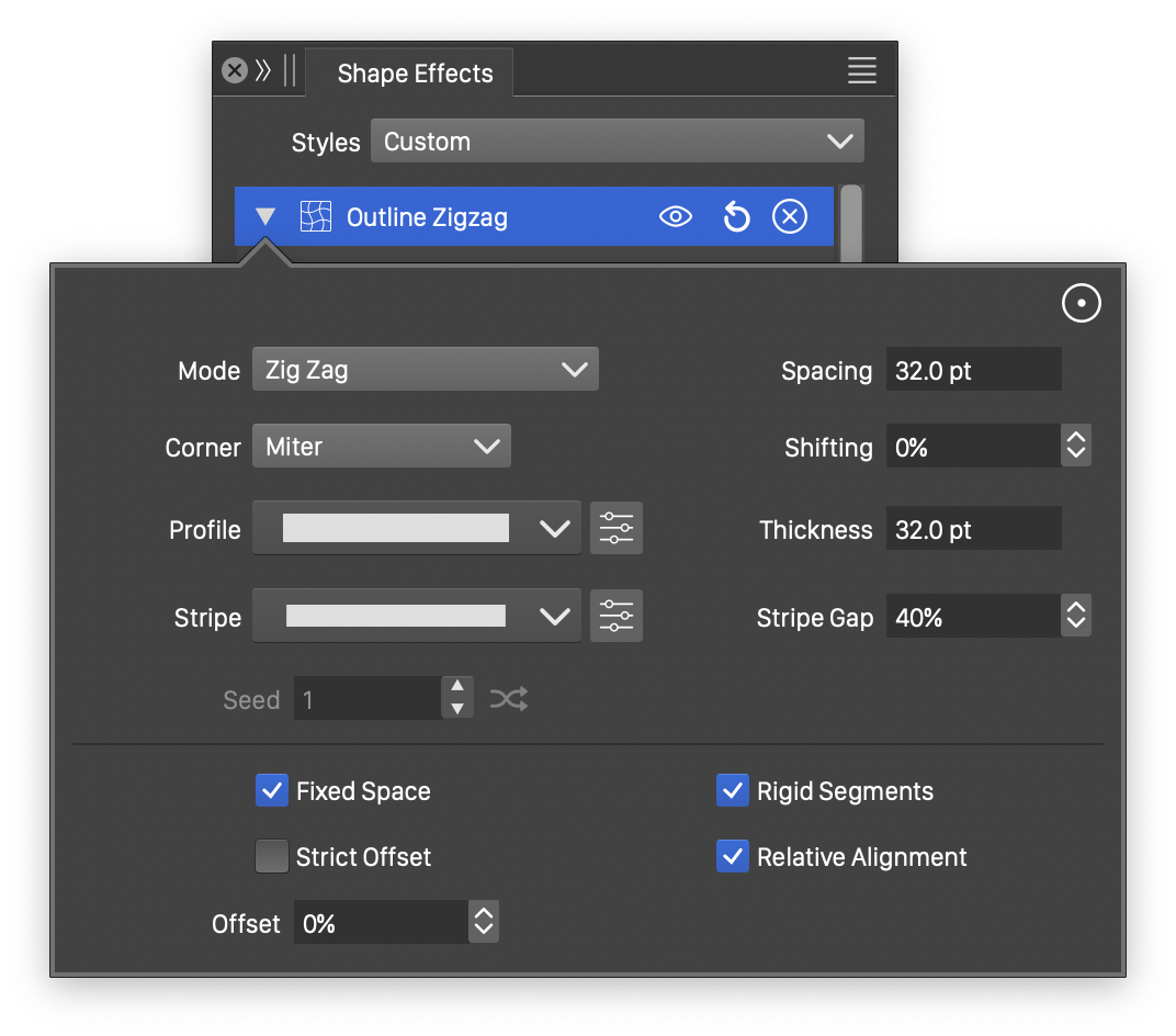
Advanced options of the Outline ZigZag effect.
The Outline ZigZag effect uses the following basic options:
- Mode - Select the outline variation mode added to the shapes. The following options are available:
- Zig Zag - Add a sharp zigzag effect to the outline shape.
- Waves - Add a smooth waving effect to the outline shape.
- Rough Line - Add sharp random line to the outline shape.
- Rough Waves - Add smooth random waves to the outline shape.
- Profile - Select the variable width profile preset or style, used to locally control the width of shape effect. The variable width profile controls the thickness of the zigzag or wave variations added to the shape. To set custom variable width profiles, click on the button, or use the primary shape effect editor tool.
- Stripe - Select or edit a stroke stripe style or preset used to create multiple parallel zigzag or wave variations of the shape. The editing and selection of stroke stripes is described in more detail in the Stroke Stripes section.
- Thickness - Set the thickness (or extent) of the shape variation.
- Spacing - Set spacing between zigzag or wave periods along the shape. Setting the Spacing is available when the Fixed Space option is checked.
- Repeat - Set the number of zigzag or wave periods along the shape, adjusting the length of a period based on the shape length. Setting the Repeat value is available when the Fixed Space option is not checked.
- Stripe Gap - Set the amount of thickness available for multiple stripes.
- Fixed Space - Enable or disable the use of fixed spacing to set the zigzag periods. When enabled, the zigzag or wave periods are set using a fixed spacing amount in the Space field. When disabled, the Repeat field is shown to set the number of zigzag or wave periods along the shape.
- Rigid Segments - Enable or disable the use of rigid segments to add zigzag or wave to the shape. When enabled, the line or curve segments of the added zigzag or wave are kept intact, and only the nodes are positioned along the shape. When disabled, the lines and curves are subdivided to create a smoother effect, resulting in curved zigzag lines.
- Strict Offset - Enable or disable the use of path offsetting to create parallel zigzag or wave shapes when stripes are used.
More advanced options of the Outline ZigZag distortion are available, by clicking on the button.
- Miter Limit - Set the miter limit angle when expanding sharp angles. Angles below this limit always result in round or bevel corners when expanded.
- Corner - Select the corner extension mode at sharp corners. The corner modes are the same as the stroke corner modes.
- Offset - Set the amount of offset along closed shapes, for the starting point of the zigzag or waving variations.
- Shifting - Set the alignment of the zigzag shapes relative to the original outline.
- Seed - Set the randomization seed used to generate the rough lines or waves. This option is enabled if the selected Mode uses randomization. The button can be used to pick random seed values.
- Relative Shift - Enable or disable relative shifting amounts.
The thickness of the outline zigzag can be edited interactively, using the primary shape effect editor tool. This includes the setting up of a variable width profile for local thickness values.
- Click on the original shape at any location and drag to set the thickness of the zigzag effect.
- If the thickness is uniform (default width profile), hold the Command (Mac) or Control (Windows) key and click at a location on the shape to add a different, non-uniform thickness at that location.
- If the thickness is non-uniform, clicking at a location will add a new width node and a local thickness amount.
- The width nodes can be dragged and positioned along the shape to set the location of various thickness amounts.
Overlay
The Overlay outline effect overlays a user selected open shape along the distorted shapes. This effect is similar to the outline zigzag effect, with the difference, that any user editable open shape can be used to create a variation along the distorted shapes.
The overlay shape can be any previously saved shape style or preset, or the shape of any object having the Shape role. The overlay shape may contain closed paths, or may be a closed shape altogether. In case of closed shapes, the overlay effect will space the overlay shape along the distorted paths using the spacing set in the advanced options.
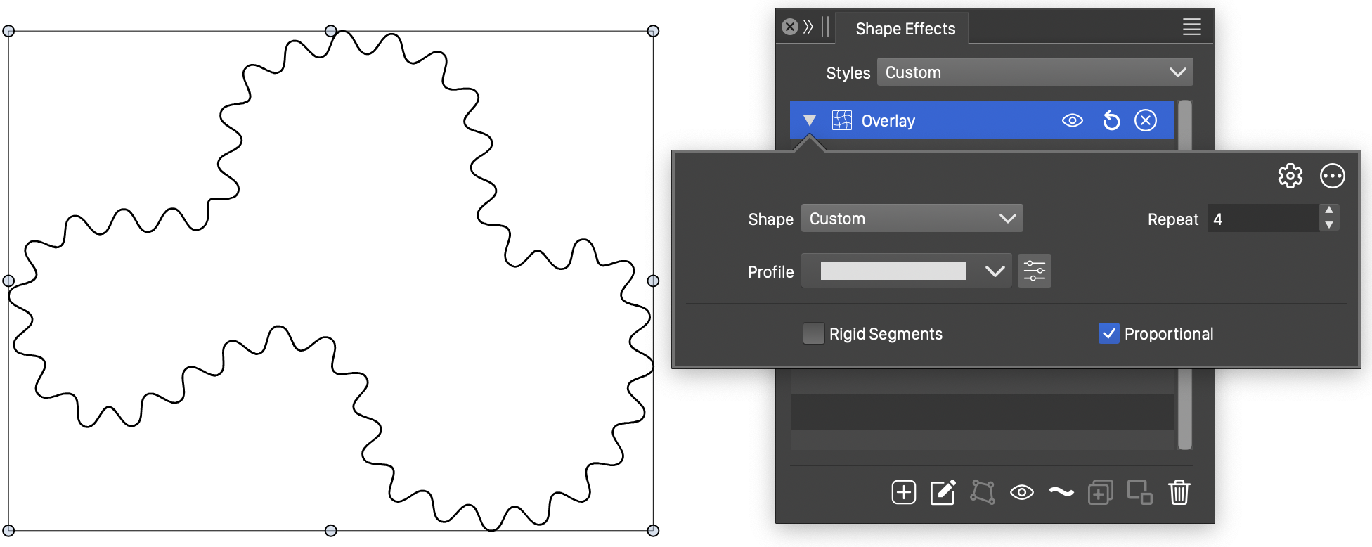
The Overlay effect, with basic options.
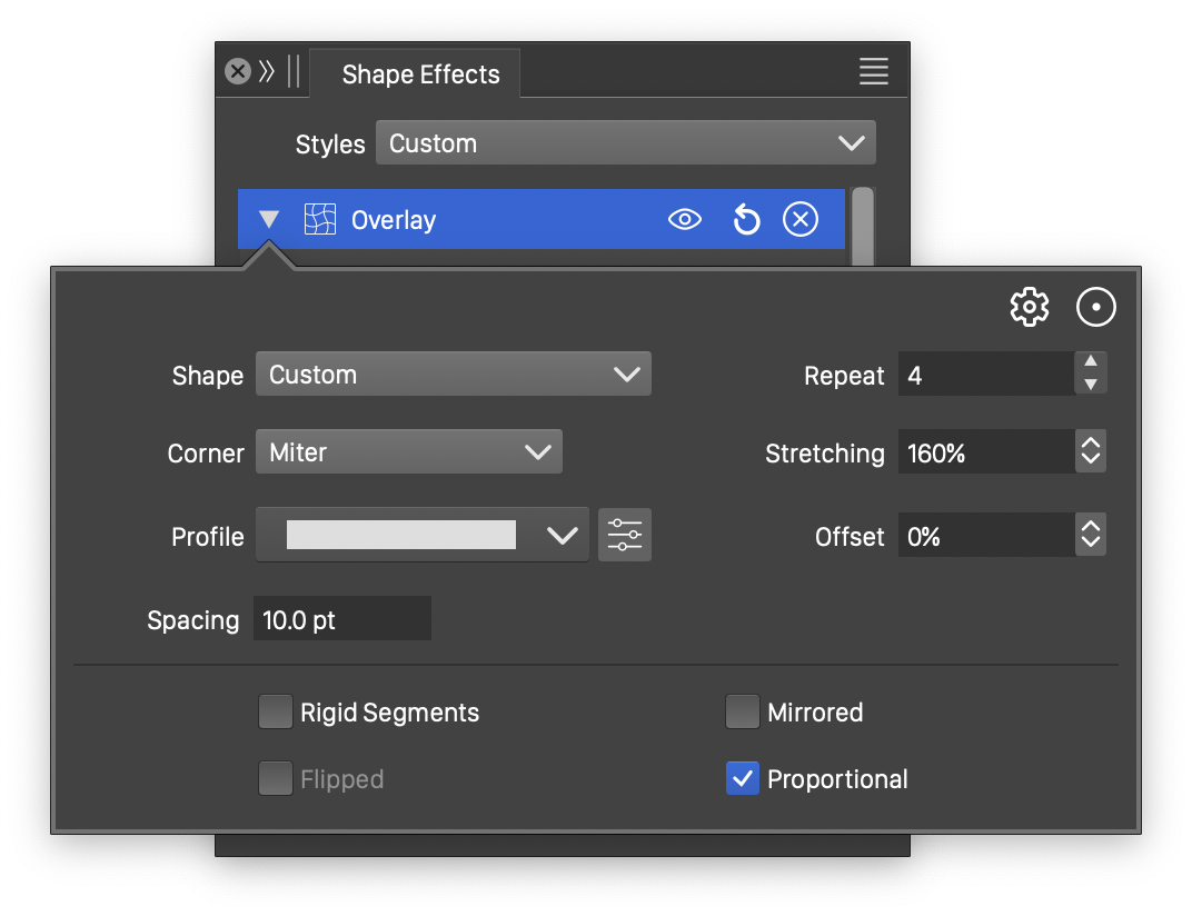
Advanced options of the Overlay effect.
The Overlay effect uses the following basic options:
- Shape - Select the overlay shape used to create variations along the distorted shapes. The overlay shape can be selected from the list of shape presets, styles and object references with the Shape role.
- Profile - Select the variable width profile preset or style, used to locally control the thickness of the shape overlay. To set custom variable width profiles, click on the button, or use the primary shape effect editor tool.
- Repeat - Set the number of times the overlay shape is stretched along the distorted shapes.
- Stretching - Set the amount of stretching of the overlay shape along the distorted shapes. The stretching amount can be set when the proportional overlay mode is enabled.
- Thickness - Set the thickness of the overlay shape along the distorted shapes. The thickness can be set when the proportional overlay mode is disabled.
- Rigid Segments - Enable or disable the use of rigid segments in the overlay shape. When enabled, the line or curve segments of overlay shape are kept intact, and only the nodes are positioned along the shape. When disabled, the lines and curves are subdivided to create a smoother effect, resulting in curved overlay shapes.
More advanced options of the Overlay distortion are available, by clicking on the button.
- Corner - Select the corner extension mode at sharp corners. The corner modes are the same as the stroke corner modes.
- Spacing - Set the spacing between closed overlay shapes. This option has an effect only when closed overlay shapes are used.
- Offset - Set the amount of offset along closed shapes, for the starting point of the overlay shape.
- Mirrored - Enable or disable the mirroring of every second overlay shape.
- Flipped - Enable or disable the flipping of mirrored overlay shapes.
- Proportional - Enable or disable the proportional stretching of the overlay shape. When stretched proportionally, the overlay shape thickness is determined by the shape height.
The thickness of the overlay shape can be edited interactively, using the primary shape effect editor tool. This includes the setting up of a variable width profile for local thickness values.
- Click on the original shape at any location and drag to set the thickness of the overlay effect.
- If the thickness is uniform (default width profile), hold the Command (Mac) or Control (Windows) key and click at a location on the shape to add a different, non-uniform thickness at that location.
- If the thickness is non-uniform, clicking at a location will add a new width node and a local thickness amount.
- The width nodes can be dragged and positioned along the shape to set the location of various thickness amounts.
Shape Corner
The Shape Corner outline effect adds corners at sharp nodes of shapes. The shape corner effect can be used to adjust corners of shapes in a group of objects, without individually setting shape corners.
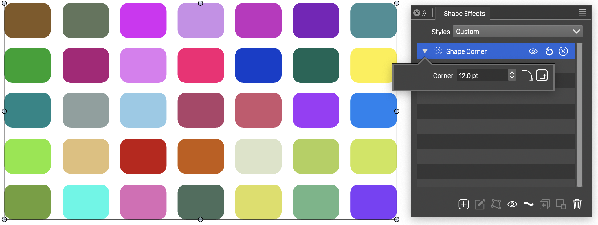
The Shape Corner effect and its options.
The Shape Corner effect uses the following options:
- Corner - Set the size of the corners at sharp nodes.
- Adaptive Corners - Check to adjust the corner sizes based on the sharpness of the corner.
 - Click to open a list of corner shapes. Custom corner shapes can be defined by the user from the Corner panel.
 - Click to open the corner options editor view, to select more options of the corner style.
Transform
The Transform outline effect adds a basic transformation to the shapes, by scaling, rotating and skewing the shape using the selected amounts.
Shape transformation options.
The Transform shape effect contains the following options:
- Angle - Set the rotation angle of the shapes.
- Scale - Set the scaling of the shapes. When the Proportional mode is disabled, the scaling is set in the Scale X and Scale Y fields.
- Skew X - Set the horizontal skewing angle.
- Skew Y - Set the vertical skewing angle.
- Proportional - Check to restrict to a proportional scaling.